Broom hanger mould

PRODUCT
MOULD
INJECTION
Broom hanger mould
PRODUCT
MOULD
INJECTION
A clamp to hang brooms and mops in the wall. Here are the steps to make its mold for the injection machine.
Browse Files
Table of Contents
Get your materials and prepare the work
Make the connection piece
Make the female mold
Plastic entrance hole
Male mold part 1
Male mold part 2
Male mold assembly
Drill the conical guides holes
Conical guides
Connect the mould
Make end caps
Cut the sides for the closing screws
Mould done!
Happy hanging :)
Make sure you have all your materials ready and go through the attached drawings and steps to understand the full picture of the process. This will help you to work more efficiently and accurate.
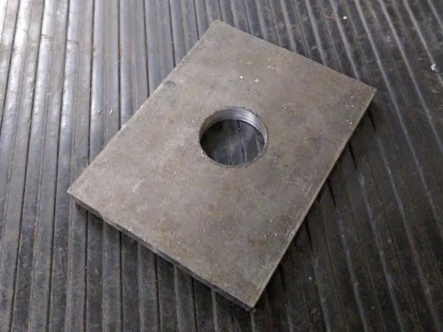
With all the parts in the bag, let’s start cutting the steel pipe nipple (no. 7) in half to make the mold nozzle. Get the metal sheet (no. 8) and turn a hole in the center with a diameter to fit one half of the steel pipe nipple in tightly. Weld the parts no. 7 and no. 8 together. Then chamfer the welded edge on the lathe.
(Drawings page 3-5)
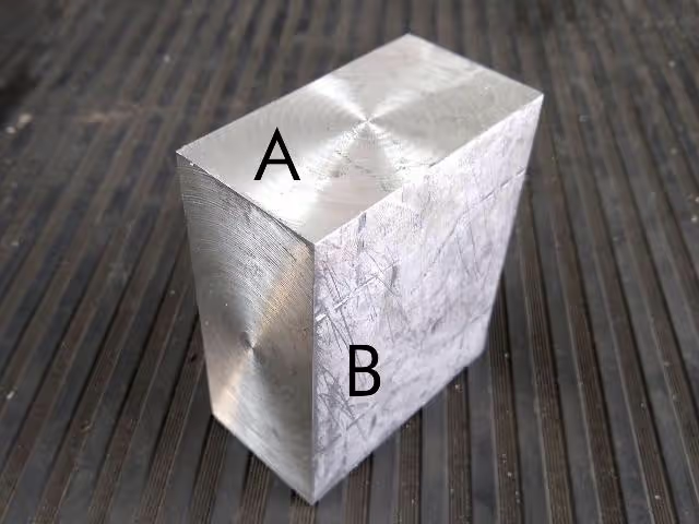
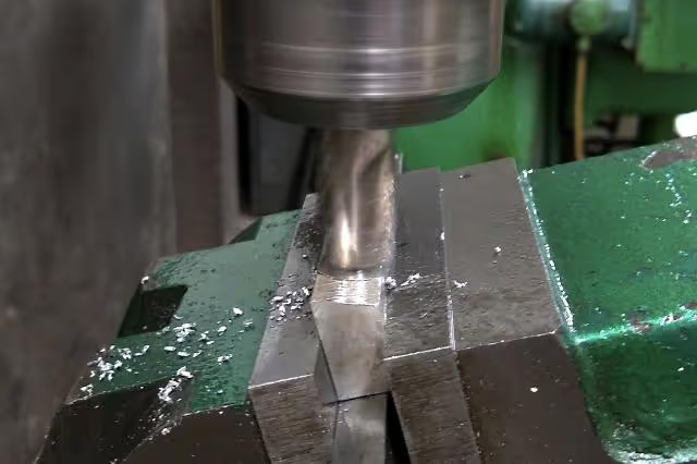
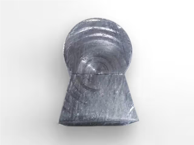
Now we’ll make the female mold. Take the aluminium block (no. 1) and drill a 1” deep hole in the center of face A of the block. Start with smaller bits until you reach the inch. Then, mill face B to open a channel of 1” wide. Use a round point bit to get a better quality finish.
(Drawings page 6)
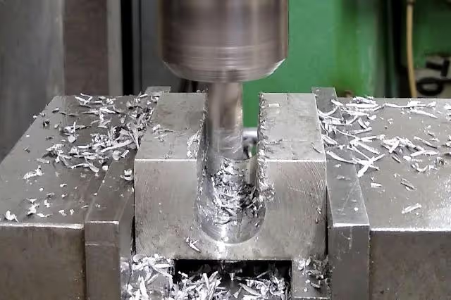
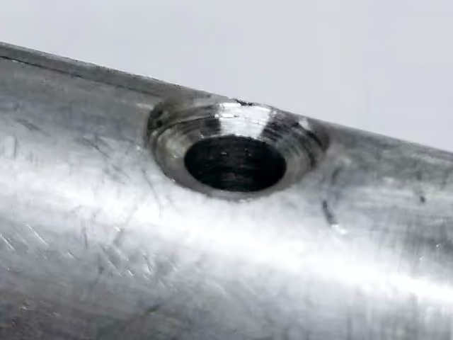
For the plastic entrance, drill a 5mm hole through the center of your female mold.
(Drawings page 6)
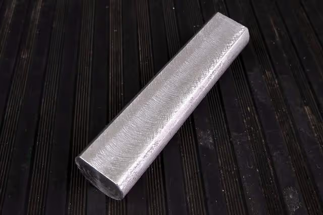
The male mold is made of three parts. Get your aluminium parts no. 2, 3 and 5 ready and start with the aluminium rod (no. 5). Mill one side of the rod to a height of 3,17mm and a width of 14,19mm.
(Drawings page 7)
Now, get part no. 3 and mill one face on an angle of 15°. Then, mill the other face to an opposite angle of 15°, until the width of the narrow face matches the face of part 5 (see last image). That should be 14,19mm in the narrower face and 21mm in the wider face.
(Drawings page 7)
To assemble the male mold, align the center of the previous parts with the center of part no. 2, press with clamps and drill two 3/16” deep holes. On part no. 5, drill flat countersinks for the screws (no. 9) head. Fix the three parts with the button head screws, washers and nuts (no. 9-11).
(Drawings pages 8-9)
Align in place the female and the male parts of the mold and fix them with a small press or locking pliers. Apply the the hole positions from the drawings to the face of part no. 2 and drill two 9,5mm diameter holes. Drill through no. 2 and 1cm deep into no.1.
(Drawings page 10)
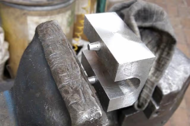
Turn your round metal bar (no. 6) to create the conical guides and saw a channel on one side to let the air flow out when inserting. With a vice or a hammer, insert the conical guides into part no.1.
(Drawings page 11)
Fix the nozzle, the female and the male parts with a small press or locking pliers, and drill four 9/32” holes through the corners of both parts. Close the mold and turn the ends to get an even surface between the male and the female parts.
(Drawings page 12)
Fix each cap (no. 4) in place and drill four 5mm diameter holes. All through the cap and 25mm deep into the female and male mold parts. Tap each hole of the female and male parts with a ¼” thread. On the caps, re-drill the holes up to ¼” and fix them with the bolts (no. 12).
(Drawings page 13)
Final step! With the hand saw, cut slots (two per side) for the bolts to fit in and out more easily. For closing the mold, four bolts and butterfly nuts (no. 13-14) will be used.
(Drawings page 14)
Mould done!
And you’re done! Here is your broom hanger mold, it's time to inject. Flexible plastics like HDPE and PP work better for the broom hangers as they won't crack during use.
To open the mold, us a flat screwdriver to pull apart the parts gently. To take out the plastic product, use the flat screwdriver or a putty knife to open and release it from the male mold. It's easier if you do this process when the plastic part is still hot, but remember to close it back to its original shape after releasing.
To install the broom hanger on the wall, drill a hole and fix it with a wall plug and a screw.
Technical drawings (pages 3–14) are critical for dimensional accuracy. Prioritize precision tools and alignment during assembly.